Slide holder on guitar headstock

I’ve gotten a couple of queries on this so I figured it was worth a post.

I’m one of those that has to have lots of thingamajigs within easy reach during a gig. Tuners, slides, capos, picks, thumbpicks, spare strings, string winders, the whole works. There’s only so much space on a music stand or on top of an amp (unless you have the fortune of playing through a Fender Twin Reverb with a roadie to lug it around) so I had to figure a way to reduce my equipment footprint.

The tuner and capo clip on to the headstock and I’m not OCD about the appearance of my instrument being cluttered with stuff, so that’s not a problem with me.  However, the slide was always a tricky one. Put it standing up anywhere and it risks being knocked over and rolling into an eternal abyss; leave it in your pocket and you’ll get some odd looks when you’re fumbling with what looks like your hands in your trousers in between songs.

So began the quest for a slide holder mounted on the guitar. A quick google search threw up a couple of options that mount conveniently behind the headstock where it’s easily accessible, but to this Cheapskate Engineer they were essentially just glorified versions of this:

It’s called a tool clip and you can get it at any decent hardware store (which is actually a bit harder to find than you might imagine, here in Singapore at least) and they’re probably a dollar for two or something like that. It already has the hole in the centre where you can screw it in, so here’s how I’ve mounted it on my Esquire:

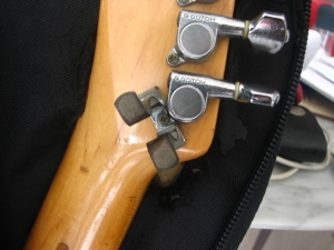
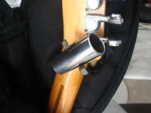
IMG_8418 IMG_8419

The tool clip slots in underneath the Gotoh machine head screw boss and I’ve used the existing screw hole. The slide fits in nicely without obstructing my left hand at the first position. As long as your machine heads have a screw of some sort onto the headstock, this can be easily adapted. Now I can grab the slide mid-solo and let loose a fiery torrent of searing slide licks (or so I’d like to imagine), then clip it back on and keep chugging out chords with all four fingers.
Foot stomp / kick drum pedal

One of my favourite blues guys is the venerable John Lee Hooker. I was probably about 16 or 17 when I was first hit by this primal force of blues power, full of raw intensity accentuated by it’s simplicity. One man, a guitar and his left foot was all that was needed to create a hypnotic syncopated beat and that left a deep impressionable on me when everyone else all around me was looking up to Steve Vai, Joe Satriani, Van Halen and Yngwie Malmsteen.

When I got around to doing acoustic blues gigs, I wanted to recreate that sound and make more racket, so here’s what I did:


It’s basically a crudely-cut plank with what used to be a headphone transducer glued on and soldered to a 3.5mm socket. You can probably get similar results with a piezo element but I didn’t have one lying around, so the old headphones became a gracious donor. Rubber strips were a necessity to keep it from wandering around on it’s own all over the stage.

I’ve used it at gigs through a DI box or plugged straight into the mixer with the high and mid frequencies turned all the way down to get more of a kick drum sound. I could have gone with one of these but hey, this is the Cheapskate Engineer and we just don’t do that sort of thing here.

Here it is in action:


Together with the bottle cap tambourine pedal:


At this gig it was going through a DI box. Be sure to work with your soundman/lady to get it (and everything else) sounding right.

MDF Desktop Stands for Monitor Speaker

In my little home setup I had a pair of speakers sitting on my desk that needed to be elevated by just enough to be in the sweet spot for a short bugger like me seated. This worked out to about 160 to 170mm from desk level, which is a rather awkward dimension for most stands on the market. Short of buying a speaker floor stand (no space), a dedicated workstation (no money) or an adjustable desktop stand (ditto), it was time to head down to the craft shop for inspiration.

As luck would have it, they had 8″ x 10″ MDF boards which were almost the exact footprint of my speakers. They also had 6″ x 4″ boards, which together with the thickness of 10mm would put me in the ballpark (6″ x 25.4 + 10mm = 162.4mm). Yeah I know working with imperial units is a bitch, you can blame the Americans for that.

I didn’t have the patience to photograph all the steps, so here’s the finished product. I think it’s straight-forward enough :


I guess this is the most stable arrangement, or least likely to collapse under the weight of the speaker. Since the load is mostly compression, white glue (something like Elmers) would suffice for putting it together without screws or nails. I used some wood sealer to prime the MDF surface before spray painting it, so that it won’t soak up the paint. This is not quite my forte so you’ll notice there are no close-up shots of the spots where I screwed up the spray painting.

So here is how it looks as part of my rig:

Rubber ducky, you’re the one…

Yeap, that’s a Fender Esquire on my wallpaper. 

By the way, those are Prodipe Ribbon 5 monitors and I highly recommend them. You won’t find ribbon tweeters in any other monitor at this price range. If you’re in Singapore, Luthermusic carries them. Save money by DIY, spend more on good gear.

DIY B-Bender continued

Alright folks as promised, here’s a video of the B-bender in action:

Haven’t quite figured out a lot of licks and chord shapes to use it with yet and I’m not quite as smooth as I should be, but I’ll get to it. Now to go get a western shirt and a country gig.

Adding aux input to an old tube radio

I’m a sucker for all things tube and I love the warmth of glowing filaments with blu-ish hues from electrons being boiled alive and going bonkers in a glass cage. Apart from guitar amplifiers, I’d always wanted to have a nice old tube radio to listen to but these seem to have sky-rocketed in price, especially FM receivers which can still be used in Singapore (no one broadcasts in AM here anymore, unless you live close to M’sia or Indonesia. More on AM and FM radio). As you might have imagined, this doesn’t really appeal to my fiscal sensibilities. Besides, I hardly ever listen to radio anyway so all I really needed was the amplifier section in an authentic looking box, to which I could hook up an auxiliary input for a Bluetooth receiver or a player of some sort.

Attempts at finding a non-functional radio for cheap to fix up were futile, but after many hours on Ebay I managed to get my hands on an old AM receiver from a local collector. This is a Philips 196A, which was designed to run on A/C or on 90V batteries (!) and be portable. The case is a cardboard box with resplendent faux leather covering and kinda looks like an old handbag that your grandma might carry to church:

This handbag doesn’t contain the usual lady’s accoutrements:

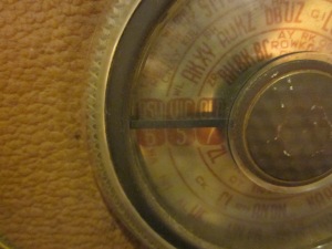
You can see that this was manufactured for use in Australia from the Aussie state initials on the station dial:


Not your usual suspects in the tube line-up (1R5, 1T4, 1S5, 3V4):

It even conveniently came with instructions on how to remove the chassis:

Circuit-wise, all that needs to be done is to feed an audio input into the grid of the first gain stage of the amplifier section, where the output of the tuner section normally goes. If that last sentence didn’t make sense, now would be a good time for a disclaimer: THESE CIRCUITS CAN CONTAIN LETHAL VOLTAGES, EVEN WHEN TURNED OFF AND NOT PLUGGED IN! IF YOU’RE NOT SURE WHAT’S GOING ON, JUST DON’T!

With that out of the way, here’s a typical circuit for a radio of this sort:

The first audio gain stage is the 1S5 and you can tell by the absence of Intermediate Frequency Transformers (IFT 1 and 2) at the plate (always check the tube datasheet). In this instance, the connection I’m looking for is conveniently located at the potentiometer (R3) that serves as a volume control.

Alright, time to get down and dirty. Some jiggling and choice swear words later, the chassis is out of the handbag and onto the bench. Cue gratuitous gut shots:


Some of these resistors and capacitors actually look good enough to eat:

The potentiometer I’m looking for is thankfully located outside of the rat’s nest that is the main circuitry. A cannibalised 3.5mm jack with the stereo signals combined via 10Kohm resistors at the potentiometer  and grounded via the shielding braid will be the auxiliary input.

And there we have it, a funky-looking player with a glorious 0.25W of output. Of course, it’s not going to blow away any audiophile set-up worth the GDP of a  small country (if any of you hi-fi nuts are reading this, don’t you have 24K gold-plated connectors to polish?) but it oozes plenty of old-school mojo.

I’m sure some of you out there are wondering…yes, you can connect a guitar input here as well (with the appropriate grid resistor) but you might want to hook it up a bigger speaker as these little ones on the radio weren’t meant to be abused.

I’ve christened it with some Bill Monroe and the Bluegrass Boys, which sounds right at home on this radio. In the meanwhile, it’s time to start planning my next misadventure into thermionic emission.

Bottle Cap Tambourine Pedal

Whenever I play as an acoustic blues duo I always try to make as much racket as I can, in the spirit of Dr Isaiah Ross:


Lugging a hi-hat around is pretty much out of the question, so I naturally went for a quick and nasty solution.

First you’ll want to polish off as many bottles of beer as you need bottle caps. This one is entirely up to you and how much racket you want to kick up, I went with 2 stacks of 3 to keep the plywood to a size that could fit into a gig bag.

Punch a hole through the centre of each bottle cap with a nail and hammer, then screw it onto the plank using a wood screw with a shaft that’s mostly unthreaded, so that the bottle caps don’t get stuck on the threads and dampen your merrymaking.

Next, you’ll want to have something springy below so that it comes back up after you step on it. I cut a piece of foam and stuck it on the bottom in unglorious fashion with masking tape:

It mic’s up pretty well if you’re playing on a bigger stage:

Un-mic-ed it can be pretty loud too for a small pub/cafe gig, here it is in action:

In that video you can faintly hear some kick-drum-ish thing going on too, that’s another pedal for another installment.

And for the record, Heineken and Carlsberg are piss. They just happened to be the only ones I had on hand at that point.

DIY Hipshot B Bender

I’m a sucker for twang, chicken picking and mechanical gadgets, so it was a no brainer that sooner or later I’d contemplate a B-bender of some sort. I’d recently acquired a G&L ASAT when I saw Will Ray’s signature model:

And I knew I had to have one. Thing is, being in Singapore I’d have to order one from overseas (not enough redneck wannabes here to justify keeping them in stock) and together with the exchange rate, it just didn’t make sense. Not to this cheapskate engineer anyway. The concept of it is pretty simple; basically a lever and fulcrum with a screw for fine adjustment to get a full step up. Here’s what the original looks like:

So I started digging around in my scrap box to see what I could use. There was some sheet aluminium that could form the base plate and a short length of hollow rectangular aluminium bar stock that I could cut to form the lever and the supports, the advantage being that it already had the right angles I needed. Not having an entire workshop at my disposal, I also had to design it to be put together with a hacksaw, a handheld power drill and thread taps. In my idle moments I put the concept together:

So with that, off I went. Unfortunately I didn’t think to take pictures of the fabrication process as I just couldn’t wait to start making aluminium dust. I had to overhaulmake some adjustments to the design along the way and here’s what it ended up becoming:

The largest change from the concept was that to avoid having the lever extend beyond the edge of the guitar (which would put plenty of  stress on the mechanism when I carry it in a gig bag), I decided to shorten the end of the lever portion and mount an extension nut parallel to the guitar so that I could screw the lever on with a nut.

This is what I mean:

It looks like the flat bar is clamping on the strap but it’s not, I’ll tell you why later. Here’s an exploded view of the components:

I used M10 for the large threaded portions, M5 for the two cap screws and M3 for mounting the U-shaped piece of sheet aluminium to the lever portion. The largest flat bar was a standard piece sold in hardware shops for fixing furniture, but these tend to be stainless steel and are an absolute bitch to file to let an M10 bolt through. You might want to hunt for something that makes your life easier.

Oh yeah, the M10 nut for the bolt going through the lever and supports should be a lock nut (the kind with nylon inserts to grip the bolt thread) because it’s going to see lots of rotating action.

I added the long M10 bolt at the end of the flar bar so that it could reach my hips when I strap on my guitar normally, otherwise I’d have to make some really obscene hip movements to get it to work. The rubber cap is to keep the bolt head from digging into my pelvic bone. Feel free to omit this bolt entirely if your gig is the kind where extreme hip gyration is highly encouraged.

Some assembly required:

You can see the two cap screws in threaded holes. The one on the left is for adjusting the travel of the lever to tune it to a proper full step up, while the other one is to adjust the default position (ie. when you’re not bending the string) so that the extension nut doesn’t rest on the mounting plate and the flat bar doesn’t rest on the strap. I used a spring to hold the former in place so that it allows easy adjustment on the fly without being too easy to turn accidentally. The other one has a nut to lock it in place since it won’t get adjusted much. And here’s the mounting plate with the supports:

All strung up and ready to go:
The key to maintaining tuning stability is to have the teflon tubing at the point where it crosses the hole in the bridge (you can just make it out above where the string exits the hole), because friction will bind the string. I managed to get some courtesy of a friend who bought a proper bender and had some to spare, but I’m told it’s found in brake cables you can buy in bicycle shops.  Me and tights don’t go well together for various anatomical reasons so I’ve never ventured into a bicycle shop to find out. If any of you can shed some light on this I’d appreciate it.
I’ll get some videos up when I can (and when I can actually play the damned thing) but in the meanwhile, hope this helps you if you’re thinking of going DIY as well. I didn’t provide any dimensions or detailed plans because I was pretty much eyeballing it and cutting on the fly. In any case, figuring it out on your own is the fun part, isn’t it?